Home

מפרק כף היד סף בילי inverter controller ic ענק צפון מערב האספסוף

High-Voltage 3-Phase Motor Driver IC with Integrated IGBT - New Industry  Products
High-Voltage 3-Phase Motor Driver IC with Integrated IGBT - New Industry Products

12V to 230V Inverter Circuit Diagram using 555 timer IC » Inverters

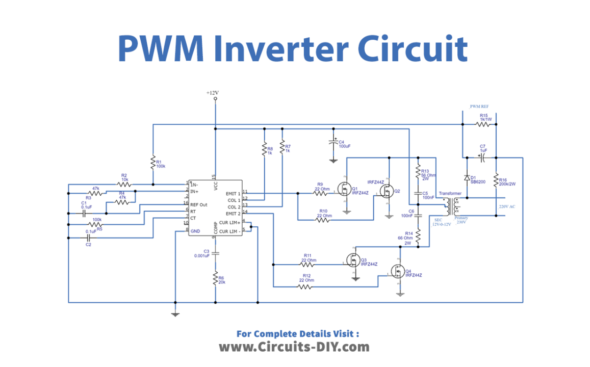
PWM Inverter Circuit

SG3525 PWM IC Pinout, Examples, Applications, Features, Datasheet

Inverter |Sanken Electric

SG3525 Inverter Driver Board - Soldering Mind

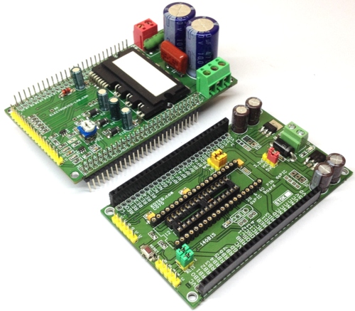
Intelligent Power Module (IPM) Board for Brushless Motors -  Electronics-Lab.com
Intelligent Power Module (IPM) Board for Brushless Motors - Electronics-Lab.com

Bridge Inverter - an overview | ScienceDirect Topics

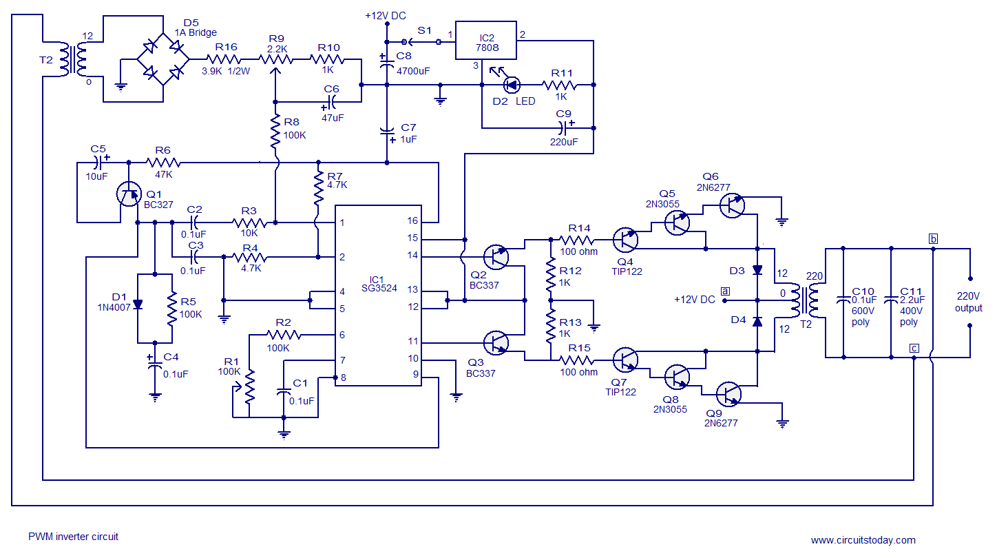
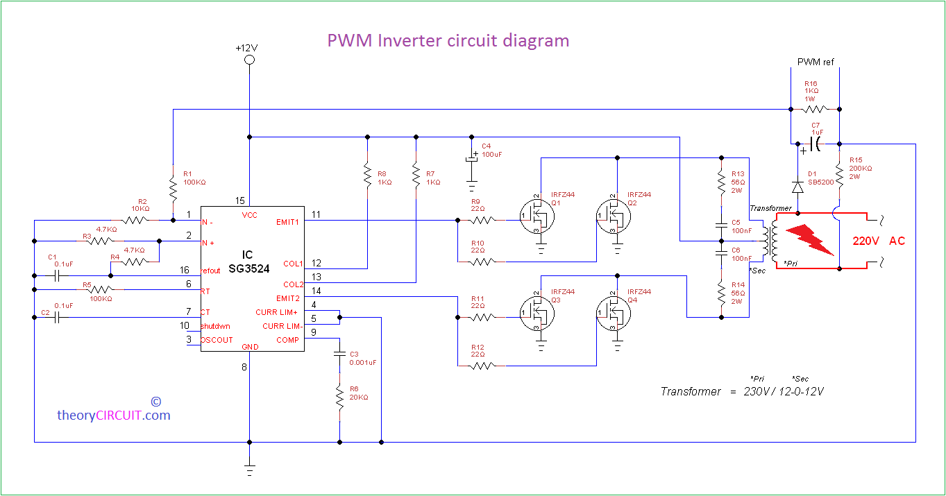
PWM inverter circuit based on SG3524 : 12V input, 220V output, 250W.

Inverter Control Card, Driver Card For Exide, V Guard, Amaron, Whirlpool,  Kevin
Inverter Control Card, Driver Card For Exide, V Guard, Amaron, Whirlpool, Kevin

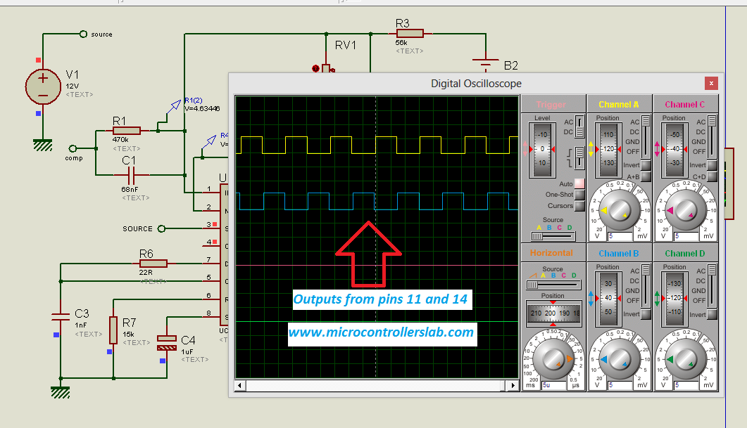
How to design a PWM control circuit using SG3525 IC | Sine wave inverter  project part 2 - YouTube
How to design a PWM control circuit using SG3525 IC | Sine wave inverter project part 2 - YouTube

Inverter control | Toshiba Electronic Devices & Storage Corporation |  Americas – United States
Inverter control | Toshiba Electronic Devices & Storage Corporation | Americas – United States

Control technique for single phase inverter photovoltaic system connected  to the grid - ScienceDirect
Control technique for single phase inverter photovoltaic system connected to the grid - ScienceDirect

SPWM driver board EGS003 for pure sine wave inverters | Shopee Philippines

PWM Inverter Circuit

Amazon.com: Sine Wave Inverter Generator Chip,EG8010 Module,23.4KHZ PWM  Carrier Frequency,5V IR2110 Pure Sine Wave Inverter Driver Board,with Dead  Zone Control : Industrial & Scientific
Amazon.com: Sine Wave Inverter Generator Chip,EG8010 Module,23.4KHZ PWM Carrier Frequency,5V IR2110 Pure Sine Wave Inverter Driver Board,with Dead Zone Control : Industrial & Scientific
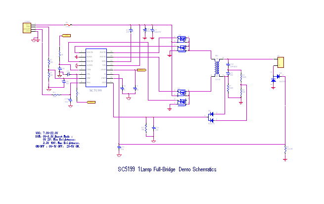
LCD Backlight Inverter Driver IC - Piezo | PIEZOCERAMICS | CERAMICS |  IGNITER | PZT | ASSEMBLY | IC | INVENTER | BIMORPH | UNIMORPH | STACK | D33  | PZT ELEMENT | SINOCERA
LCD Backlight Inverter Driver IC - Piezo | PIEZOCERAMICS | CERAMICS | IGNITER | PZT | ASSEMBLY | IC | INVENTER | BIMORPH | UNIMORPH | STACK | D33 | PZT ELEMENT | SINOCERA

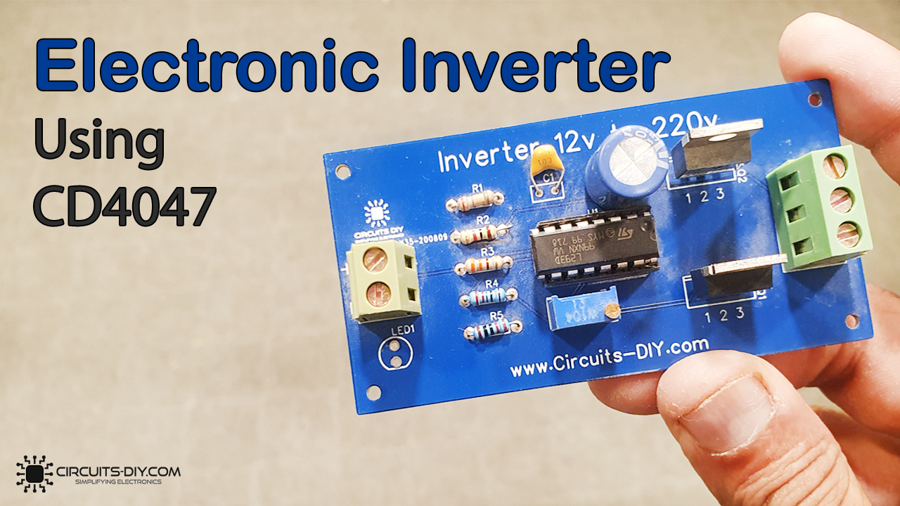
12v DC to 220v AC Inverter Circuit using CD4047 IC

DIY Cheap 1000W Pure Sine Wave Inverter (12V to 110V/220V) : 26 Steps (with  Pictures) - Instructables
DIY Cheap 1000W Pure Sine Wave Inverter (12V to 110V/220V) : 26 Steps (with Pictures) - Instructables

Easily Boost 12V to 140V with a Single Converter IC | Analog Devices

Circuit diagram of stand-alone inverter with proposed controller. |  Download Scientific Diagram
Circuit diagram of stand-alone inverter with proposed controller. | Download Scientific Diagram

PWM Inverter Circuit Diagram using TL494

Inverter PIC Microcontroller

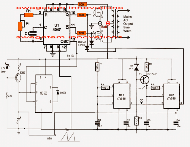
Pure Sine Wave Inverter Circuit Using IC 4047 | Homemade Circuit Projects

Inverter control | Toshiba Electronic Devices & Storage Corporation |  Americas – United States
Inverter control | Toshiba Electronic Devices & Storage Corporation | Americas – United States

Solar Inverter Circuit Diagram By Using 555 IC Timer - Electronic Projects,  Power Supply Circuits, Circuit Diagram symbols, Audio Amplifier Circuit pdf  & Engineering Projects
Solar Inverter Circuit Diagram By Using 555 IC Timer - Electronic Projects, Power Supply Circuits, Circuit Diagram symbols, Audio Amplifier Circuit pdf & Engineering Projects